Dsc Serial Protocol Rs232
RS232 is one of the most widely used techniques to interface external equipment with computers. RS232 is a Serial Communication Standard developed by the Electronic Industry Association (EIA) and Telecommunications Industry Association (TIA). RS232 defines the signals connecting between DTE and DCE. Here, DTE stands for Data Terminal Equipment and an example for DTE is a computer. DCE stands for Data Communication Equipment or Data Circuit Terminating Equipment and an example for DCE is a modem. RS232 was introduced in 1960’s and was originally known as EIA Recommended Standard 232. RS232 is one of the oldest serial communication standards with ensured simple connectivity and compatibility across different manufacturers. Originally, the DTEs in RS32 are electromechanical typewriters and DCEs are modems. RS232 uses serial communication, where one bit of data is sent at a time along a single data line. This is contrast to parallel communication, where multiple bits of data are sent at a time using multiple data lines. The advantage of using serial communication over parallel communication is the number of wires required to make a full duplex data transmission will be very less (two wires are sufficient without considering electrical lines). RS232 has become a de facto standard for computer and instrumentation devices since it was standardised in the year 1962 by EIA and as a result, it became the most widely used communication standard. But the main drawback of RS232 standard is data rate and length of cable. RS232 supports a maximum baud rate of 19200 bps and the maximum length of the cable is 20 meters.
Load Cell Central will help assess factors — including physical installation needs, communications protocol and output requirements — to direct you to the device best suited to your application. The DSC series of load cell / scale digitizing units offer ASCII, Modbus, RS232, RS485, and MantraCAN outputs.
What is RS232?
Officially, the RS232 standard is called EIA/TIA – 232 and is defined as the interface between a DTE and a DCE devices employing serial binary data interchange. RS232 is considered to be a appropriate standard. This is because RS232 ensures that there is no conflict between the DTE and DCE devices by specifying:
Cossacks: back to war multiplayer. Cossacks: Back to War Free Download PC Game Cracked in Direct Link and Torrent. Cossacks: Back to War – To stand alone in war is extremely unpleasant. Extremely pleasant, on the other hand, is the stand-alone version Cossacks: Back to War. Containing all of. CRACKED – FREE DOWNLOAD – TORRENT. Download Cossacks: Back to War. Build a strong empire that's on a quest to conquer land in Russia and Asia. You can download this game in following steps. First Download Cossacks Back to War by click on download link. Unzip File Using 'Winrar'. Open 'Cossacks Back to War.CheckGamingZone' 'Game' Folder. Click on 'Setup' and install it. Open 'Crack' folder, copy all files and paste it where you install the game. Cossacks: Back to War Game, PC download, full version game, full pc game, for PC Before downloading make sure that your PC meets minimum system requirements.
- Electrical Specifications
- Mechanical Specifications
- Functional Specifications and
- Procedural Specifications
All these specifications provide us different parameters like common voltage levels, signal levels, pin wiring specifications, control data between the host device and its peripheral etc. Let us see about the different specifications in detail.
Electrical Characteristics
The electrical characteristics of RS232 defines the specifications related to voltage levels, line impedance and rate of change of signal levels.
Voltage Levels
RS232 was defined way before TTL logic and hence, it is not unexpected that RS232 doesn’t use the TTL specific 5V and GND logic levels.
Armory of Tamriel 101 Full Version Weapons only- Version 200 beta is now available for download on the front page. Skyrim mod categories. Mod created by the Armory of Tamriel Team,-Baratan (ByblosHex)-Albatross-Arctorius-ishmaeltheforsaken Featuring, 'Better Shaped Weapons' meshes by,-LeanWolf 'Maker's Mark Ingots' By,-Omni Mike Special Thanks to,-Bethsoft Game Studio-Our Fans on the Bethsoft forums & The Skyrim Nexus for their endless support!
The logic ‘1’ in RS232 is described as being in the voltage range of -15V to -3V and logic ‘0’ is described as the voltage range of +3V to +15V i.e. low level voltage is logic ‘1’ and high level voltage is logic ‘0’.
Typically, the logic ‘1’ in RS232 will be -12V and logic ‘0’ will be +12V. All the above mentioned voltages are with respect to a common ground ‘GND’ pin. Any voltage between -3V and +3V is considered to be an undefined logic state.
Historically, logic ’1’ (-15V to -3V) is referred to as Marking and logic ‘0’ (+3V to +15V) is referred to as Spacing.
Slew Rate
The other important electrical characteristic is the rate of change of signal levels i.e. the Slew Rate. The maximum slew rate in RS232 is limited to 30V/µs. Also, a maximum bit rate of 20 Kbps is also defined.
These limitations of the standard help in reducing the cross – talk with adjacent signals.
Line Impedance
The line impedance i.e. impedance of the wire between the DTE and DCE devices is specified to be around 3Ω to 7Ω.
Also, the original RS232 standard specifies the maximum length of the cable as 15 meters but the revised standards specify the maximum length in terms of capacitance per unit length.
Mechanical Specifications
The Mechanical Specifications of RS232 covers the mechanical interface of the standard. The RS232 standard specifies a 25 – pin D – Type connector to support the full functionality of RS232.
The following image shows a DB25 Connector. The DTE device uses a female outer casing with male pins and the DCE device uses a male outer casing with female pins.
There are three types of signals in RS232. They are data, control and ground. The following table shows the list of pins, their direction in communication along with their signal type.
As the electronic equipment and devices are getting smaller, we do not have room for larger connector like DB25 and most common applications do not require all the 25 pins in the connector. Hence, a reduced function 9 – pin connector is used commonly.
The 9 – pin connector is called as DE-9 (often wrongly called as DB-9) and it is a D – Type subminiature (D- Sub) connector. The following image shows the DE-9 male and female connectors.
The pins in DE-9 connector, their names and description are given in the following table.
Functional Specifications
Since RS232 is considered a complete standard, it defines more than electrical and mechanical characteristics. RS232 standard also defines the functions of different signals used in the interface.
The signals are classified as: Common, Data, Timing and Control Signals.
Procedural Specifications
The Procedural Specifications of RS232 specify the sequence of operations that must be carried out when a DTE and DCE are connected.
Assume a computer (DTE) is connected to a Modem (DCE) through RS232 interface. In order to send data from computer to Modem, the following procedure must be followed.
- When Modem (DCE) is ready to receive, it will send a DCE ready signal.
- When the computer (DTE) is ready to send the data, it sends a Ready to Send (RTS) signal.
- The Modem (DCE) then sends a Clear to Send (CTS) signal to indicate that data can be sent by computer (DTE).
- Finally, the Computer (DTE) sends data on Transmit Data (TD) line to the Modem (DCE).
NOTE: This is not an exact procedure but similar to the actual one.
Practical Implementation of RS232
The voltage levels of RS232 are very different from most of the systems designed today. Hence, we need a level converter of some sorts to implement RS232 interface. This job is performed by dedicated level converter ICs like MAX232 by Maxim Integrated for example.
These ICs take in the RS232 signals and generate a TTL level voltages. These ICs also invert the signals as low voltage levels in RS232 are logic ‘1’ and high voltage levels in RS232 are logic ‘0’. The following image shows the implementation of RS232 Driver in a real time application.
Here, the UART (Universal Asynchronous Receiver Transmitter) generates and receives the necessary signals for serial communication and the RS232 Driver is responsible for converting signals between TTL and RS232 interface.
The communication system mentioned in this example is of asynchronous type and it requires synchronization bits i.e. Start and Stop and error checking bit i.e. Parity. The UART in the above example is responsible for generating the Start, Stop and Parity bits when transmitting the data and also detecting errors while receiving data.
The following image illustrates a typical RS232 application between a Computer and a Modem. Here, the PC or Computer is the DTE and the Modem is the DCE.
The Computer and Modem communicate with each other using RS232 interface and the communication between the modems is established using telecommunication links.
How RS232 Works?
In RS232, the data is transmitted serially in one direction over a single data line. In order to establish two way communication, we need at least three wires (RX, TX and GND) apart from the control signals. A byte of data can transmitted at any time provided the previous byte has already been transmitted.
RS232 follows asynchronous communication protocol i.e. there is no clock signal to synchronize transmitter and receiver. Hence, it uses start and stop bits to inform the receiver when to check for data.
There is a delay of certain time between the transmissions of each bit. This delay is nothing but an inactive state i.e. the signal is set to logic ‘1’ i.e. -12V (if you remember, logic ‘1’ in RS232 is -12V and logic ‘0’ is +12V).
First, the transmitter i.e. the DTE sends a Start bit to the receiver i.e. the DCE to inform it that data transmission starts from next bit. The Start bit is always ‘0’ i.e. +12V. The next 5 to 9 characters are data bits.
If parity bit is used, a maximum of 8 bits can be transmitted. If parity isn’t used, then 9 data bits can be transmitted. After the data is transmitted, the transmitter sends the stop bits. It can be either 1 bit or 1.5 bits or 2 bits long. The following image shows the frame format of the RS232 protocol.
Though RS232 is considered to be a complete standard, many manufacturers may not abide by the standards. Some manufacturers may implement the complete specifications and some implement just a partial specification.
The reason behind this variation in implementation of the RS232 standard is that not all devices and applications require the full specifications and functionality of the RS232 Protocol. For example, a serial Modem using RS232 may require more control lines than a serial Mouse using serial port.
Then how does the Transmitter and Receiver, which might use different set of specifications, successfully transmit or receive the data? A process called Handshaking is used for this purpose.
Handshaking

Handshaking is a process of dynamically setting the parameters of a communication between the transmitter and receiver before the communication begins.
The need for handshaking is dictated by the speed at with the transmitter (DTE) transmits the data, the speed at which the receiver (DCE) receives the data and the rate at which the data is transmitted.
In an asynchronous data transmission system, there can be no handshaking, hardware handshaking and software handshaking.
No Handshaking
If handshaking is not used, then the receiver (DCE) must read the data that is already received by it before the transmitter (DTE) sends the next data. For this, the receiver uses a special memory location called Buffer and since it is used at receiver end, it is called Receiver Buffer.
The received data is stored in the buffer before it is read by the receiver. The Receiver Buffer can typically store a single bit of data and this data must be cleared (read) before the next data arrives and if it is not cleared, the existing data will be overwritten with the new data.
The following image shows a typical transmission and reception of data using transmitter and receiver buffers. In this setup, the receiver has successfully read the first three bits of data but did not read the fourth bit. Hence, the next bit i.e. the fifth bit will overwrite the fourth bit and the fourth bit is lost.
To avoid situations like this, we need some sort of Handshaking mechanism (either Software or Hardware Handshaking).
Hardware Handshaking
In Hardware Handshaking, the transmitter first asks the receiver whether it is ready to receive the data. The receiver then checks its buffer and if the buffer is empty, it will then tell the transmitter that it is ready to receive.
The transmitter will transmit the data and it is loaded into the receiver buffer. During this time, the receiver tells the transmitter not to send any further data until the data in the buffer has been read by the receiver.
The RS232 Protocol defines four signals for the purpose of Handshaking:
- Ready to Send (RTS)
- Clear to Send (CTS)
- Data Terminal Ready (DTR) and
- Data Set Ready (DSR)
The following image shows the connection between a 9 – pin Transmitter (DTE) and 25 – pin Receiver (DCE) and a 9 – pin Transmitter and a 9 – pin Receiver in hardware handshaking mode.
With the help of Hardware Handshaking, the data from the transmitter is never lost or overwritten in the receiver buffer. When the transmitter (DTE) wants to send data, it pulls the RTS (Ready to Send) line to high.
Then the transmitter waits for CTS (Clear to Send) to go high and hence it keeps on monitoring it. If the CTS line is low, it means that the receiver (DCE) is busy and not yet ready to receive data.
When the receiver is ready, it pulls the CTS line to high. The transmitter then transmits the data. This method is also called as RTS/CTS Handshaking.
Additionally, there are two other wires used in Handshaking. They are DTR (Data Set Ready) and DSR (Data Set Ready). These two signals are used by the DTE and DCE to indicate their individual status. Often, these two signals are used in modem communication.
The newer standards of RS232 define an 8 signal Hardware Handshaking.
Software Handshaking
Software Handshaking in RS232 involves two special characters for starting and stopping the communication. These characters are X-ON and X-OFF (Transmitter On and Transmitter OFF).
When the receiver sends an X-OFF signal, the transmitter stops sending the data. The transmitter starts sending data only after it receives the X-ON signal.
Limitations of RS232
- RS232 Protocol requires a common ground between the transmitter (DTE) and receiver (DCE). Hence, the reason for shorter cables between DTE and DCE in RS232 Protocol.
- The signal in the line is highly susceptible to noise. The noise can be either internal or external.
- If there is an increase in baud rate and length of the cable, there is a chance of cross talk introduced by the capacitance between the cables.
- The voltage levels in RS232 are not compatible with modern TTL or CMOS logics. We need an external level converter.
Applications
- Though RS232 is a very famous serial communication protocol, it is now has been replaced with advanced protocols like USB.
- Previously they we used for serial terminals like Mouse, Modem etc.
- But, RS232 is still being used in some Servo Controllers, CNC Machines, PLC machines and some microcontroller boards use RS232 Protocol.
There are many kinds of serial interfaces in the market today. Two of the oldest serial interfaces are. Both RS232 and RS485 are widely used in many applications.RS-232 is best for short-distance low-speed requirements. It is simple and low cost, and plenty of components like line drivers and receivers, UARTs, and connectors are available to build the interface. RS-232 only allows for one transmitter and one receiver on each line. RS-232 also uses a Full-Duplex transmission methodThe RS-485 is for higher speeds over longer ranges or if duplex networking capability is required.
Again, many standard parts are available to create the interface. RS-485 was made to address the multi-drop limitation of RS-422, allowing up to 32 devices to communicate through the same data line.
Any of the slave devices on an RS-485 bus can communicate with any other 32 slave devices without going through a master device.For more information, please visit or email to sales@sopto.com.Tags.
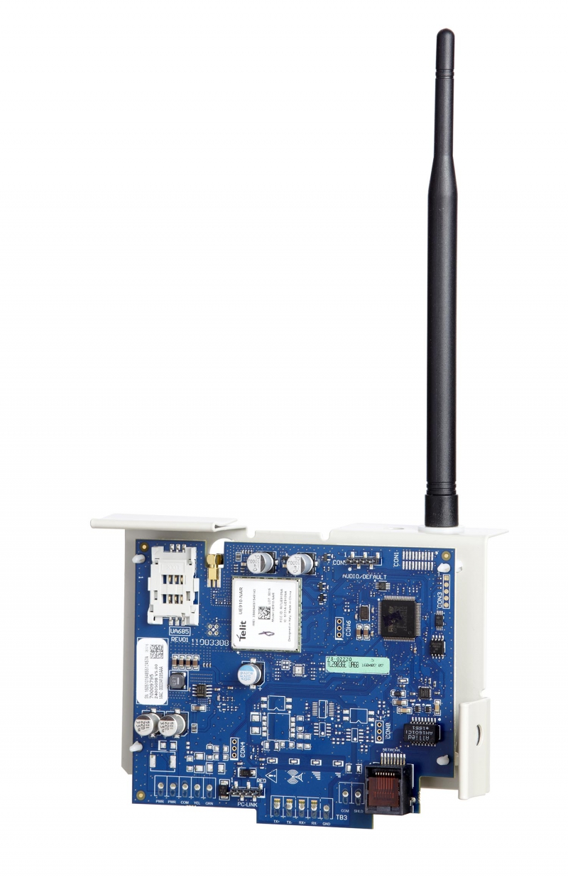
The DSC TL280LER-AT is a wireless AT&T LTE/HSPA/Internet/Cellular/Dual-Path alarm communicator with RS-232 serial connection, that is compatible with the DSC PowerSeries Neo control panels. The TL280LER-AT ensures reliable back up alarm communication of the phone line for your home or business.When the TL280LER-AT is connected to the PC-Link connector on a DSC HS2016/HS2032/HS2064/HS2128 control panel(s), the alarm reporting paths can be combined through the Public Switched Telephone Network (PSTN), if so desired, plus the cellular network and internet for increased redundancy to the GeoArm central monitoring station. It conveniently utilizes the cellular network and Internet as back-up to ensure high speed, reliable and secure alarm communications to alleviate any concerns about the possibility of phone line disruption.With 128-bit AES encryption of the alarm signal, central stations, and DIYer's can be assured that this is the most secure alarm communicator offered. And with programmable (by seconds) supervision heartbeats, the LE2080R-AT communicator's availability is fully monitored.
The TL280LER-AT offers full data reporting and remote management which saves time and reduces the maintenance costs. Also, the TL280LER-AT is used as a fundamental tool to deliver visual verification to reduce the high costs that can be incurred by false alarms and unnecessary site-checks.As more and more homes or businesses move away from traditional phone lines, towards VoIP (Voice over IP) or mobile phones, alternate delivery methods for alarm communication must be explored for security systems. The TL280LER-AT conveniently utilizes the cellular and internet network to reduce the need for dedicated phone lines and/or the impact of phone line interruption.
Rs232 Protocol
Dimensions (metal enclosure): 5.875' W x 4.5' D (150mm x 115mm). Weight: 320 g (with mounting bracket).
Input Voltage: 10.8 - 12.5 VDC. Current Draw (Standby): 100 mA (internet only). Current Draw (Standby): 120 mA (internet and cellular).
Usb To Rs232 Serial Adapter
Alarm (Transmitting) Current: 400 mA. LTE Bands: B2, B4, B5, B12, B13. Operating Frequency: 850MHz, 900MHz, 1800MHz, 1900MHz, 2100MHz. Operating Environment: 40° to 104°F (5° to 40°C). Relative Humidity: 5-93% Maximum (non-condensing). Antenna Gain: 2.0dBi. Approvals Listings: FCC/IC, PTCRB, UL/ULC, CSFM.
- среда 15 апреля
- 14